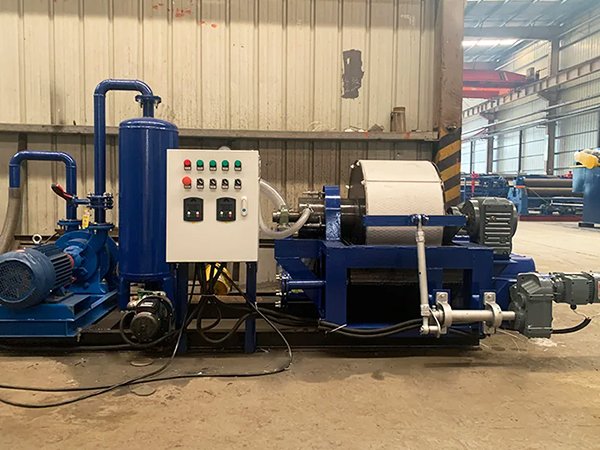
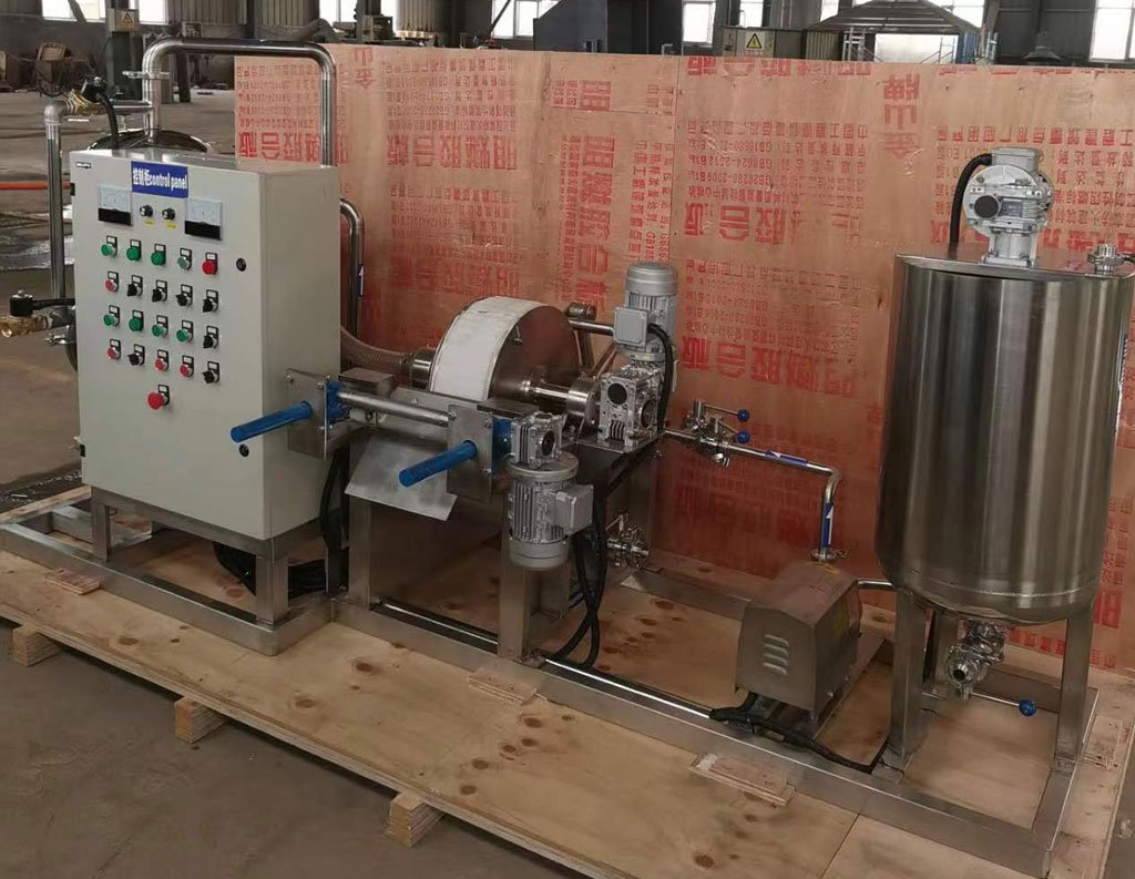
Laboratory-Scale Vacuum Rotary Drum Filter
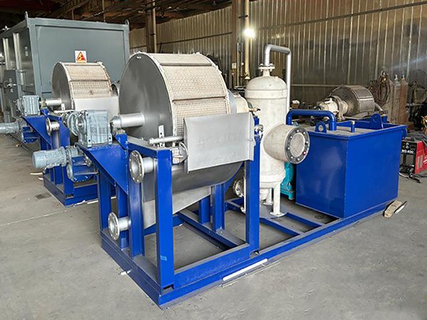
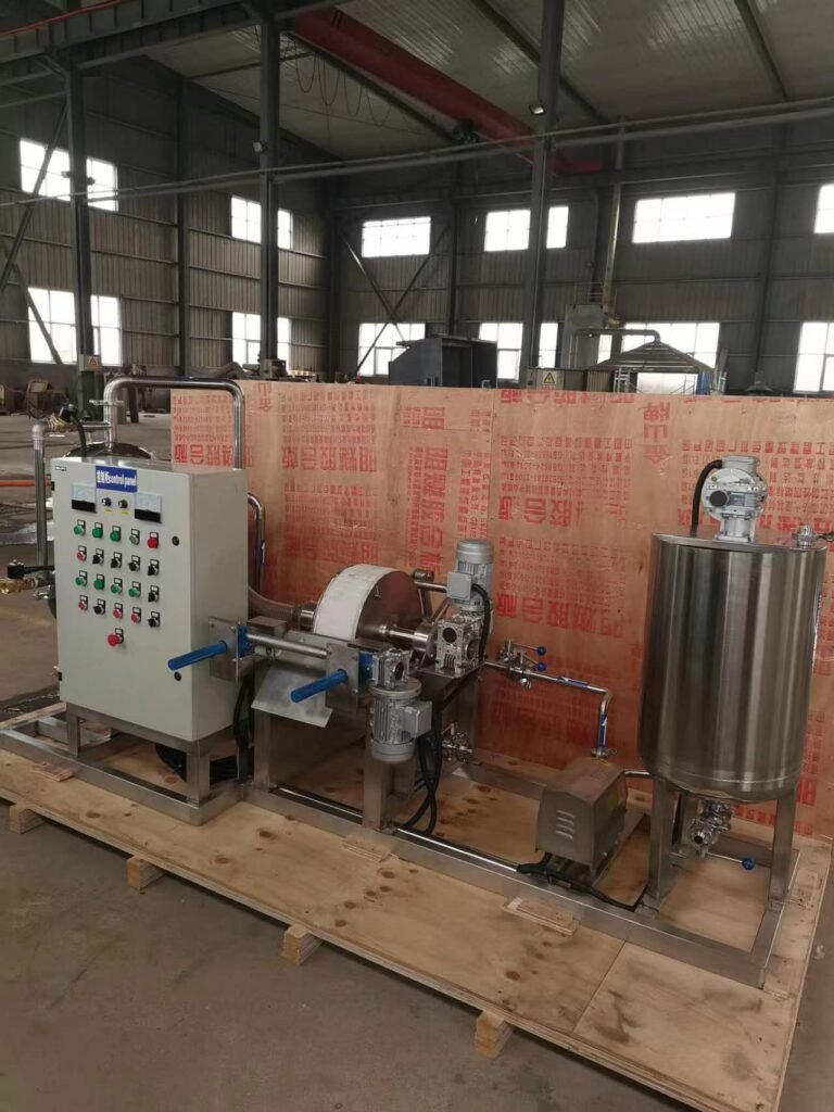
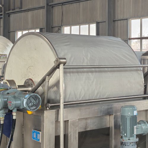
The Laboratory-Scale Vacuum Rotary Drum Filter is a small-scale, batch or semi-continuous experimental device for solid-liquid separation. It is mainly used in process development, feasibility testing, and educational demonstrations.
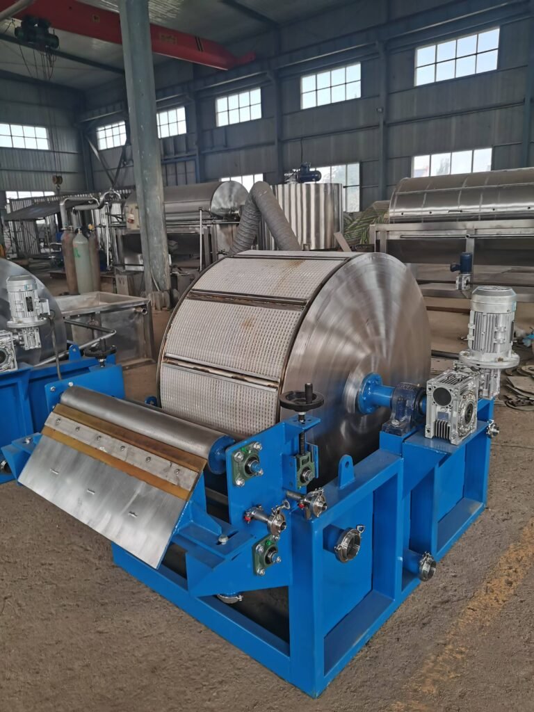
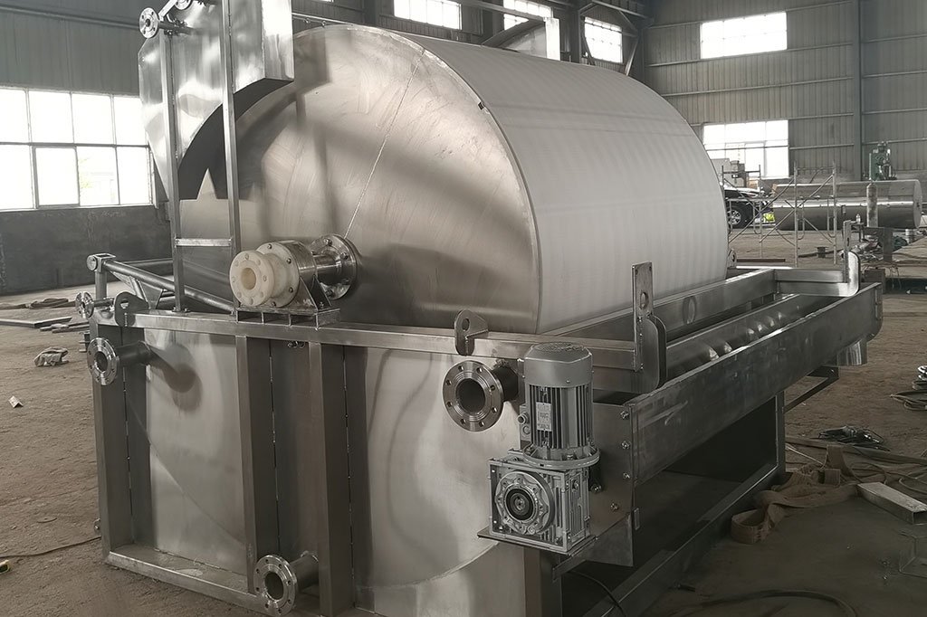
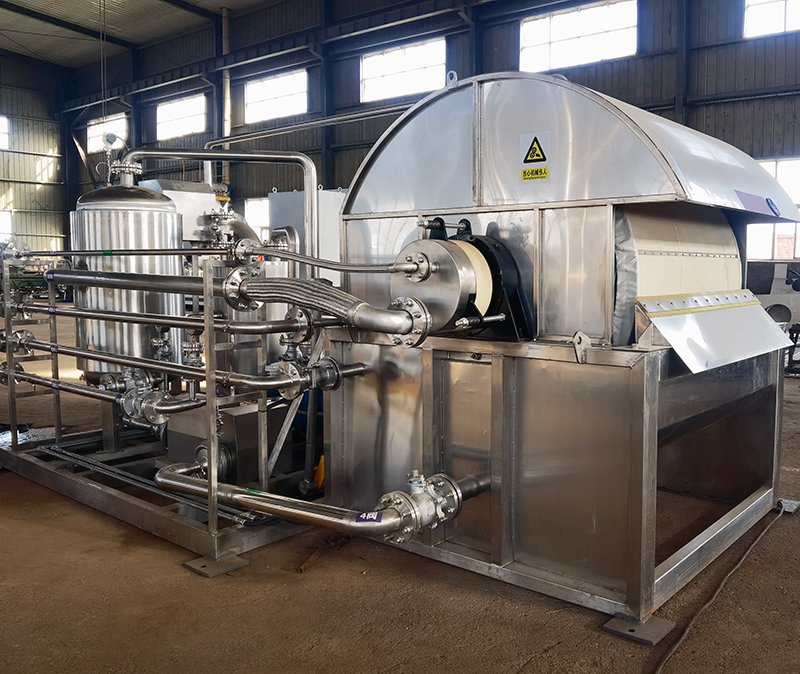
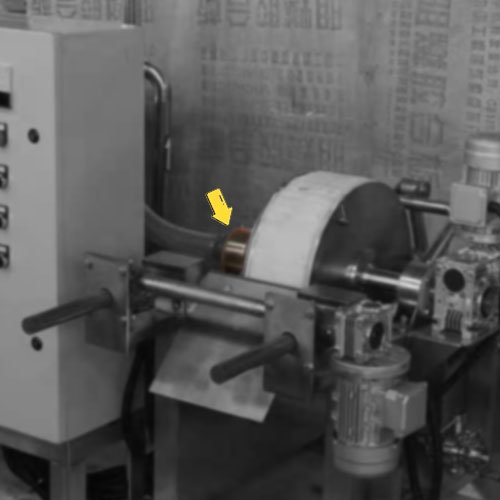
It is a miniaturized device that simulates the operation of large-scale industrial vacuum drum filters. Its core design features a horizontal cylindrical drum, which is partially submerged in a slurry tank and has a cake coated on its surface.
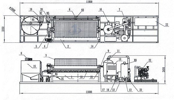
Main components
Compact structure, flexible operation, and low slurry demand (typically only a few liters). It can simulate multiple continuous industrial filtration units on a single small device.
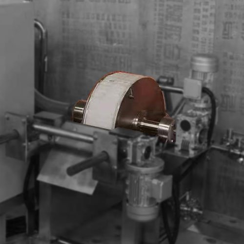
Drum
Typically constructed from stainless steel or corrosion-resistant materials, it has a relatively small diameter (commonly ranging from 100mm to 300mm) and its interior is divided into several fan-shaped compartments. Each compartment is connected via a pipeline to a distribution head valve located on the hollow journal of the drum.
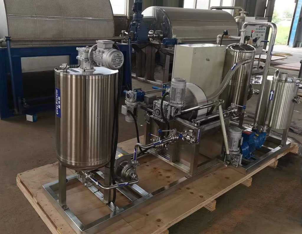
Slurry Tank
A tank that holds the suspension (slurry) to be filtered. It is typically equipped with an agitator to prevent the sedimentation of solid particles and ensure uniform filtration concentration.
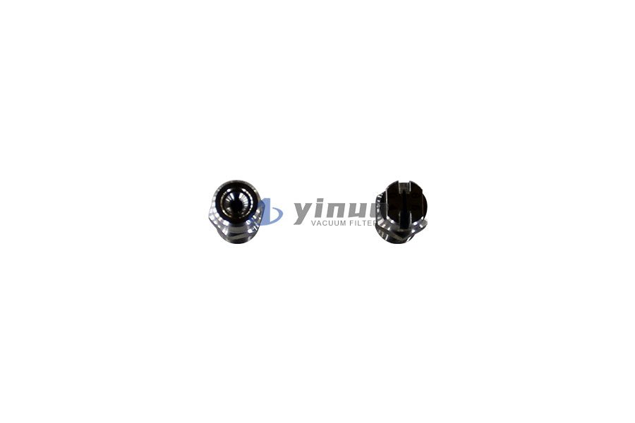
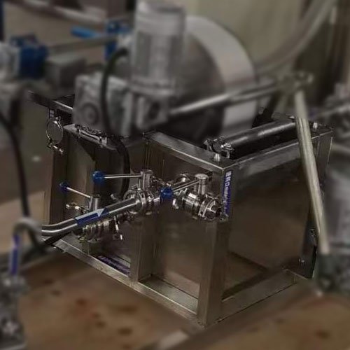
Distributor Valve
Distributor Valve (also known as a Diaphragm Valve): This is a critical component of the equipment. It is fixed in place and fits tightly with the drum’s journal. Through the distributor valve, different areas of the drum can be controlled to connect sequentially to a vacuum source or a compressed air source, enabling cyclic operations such as filtration, drying, washing, and discharging.
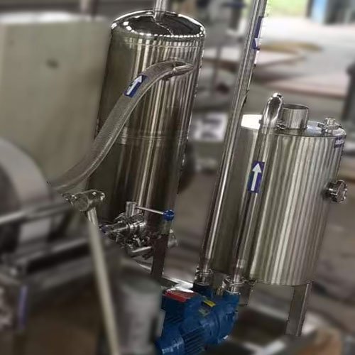
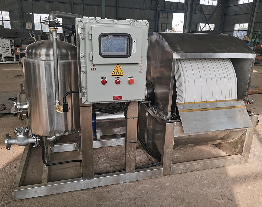
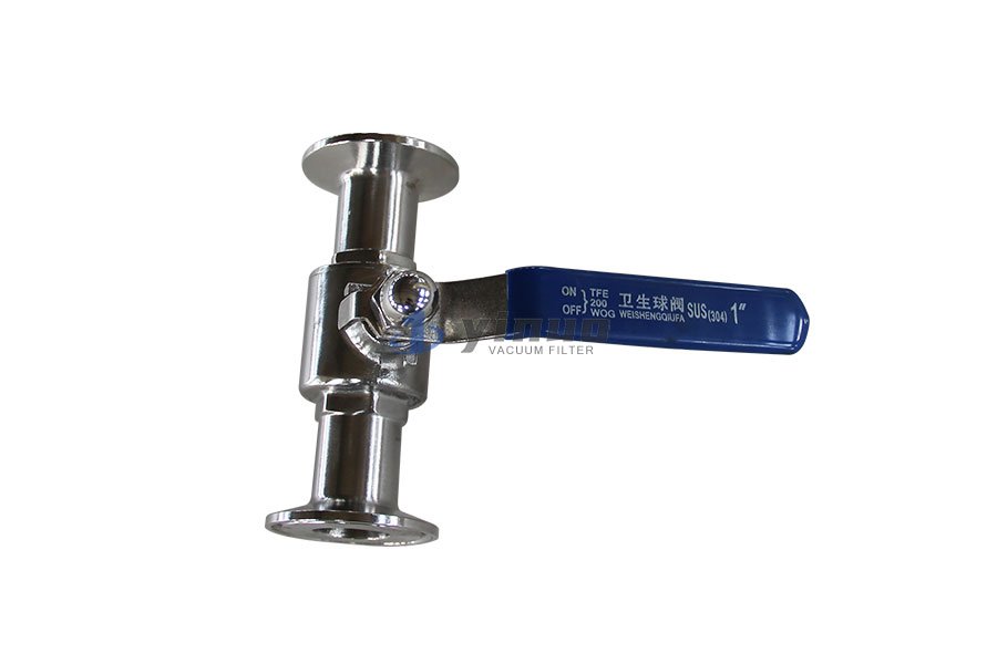
Vacuum System
Vacuum System: Typically consisting of a vacuum pump, a buffer tank (vacuum receiver tank), a vacuum gauge, and piping, it provides the necessary negative pressure power for filtration.
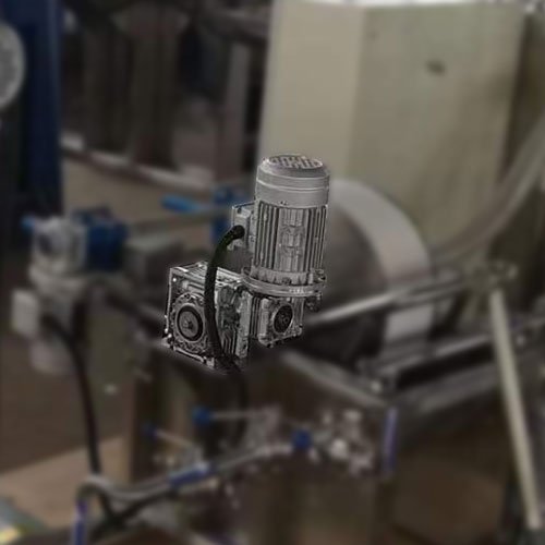
Drive System
A small motor and reduction gear mechanism that drives the drum to rotate at a constant, very slow speed (typically adjustable, e.g., 0.1 to 2 rpm).
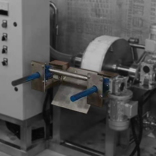
Discharge Mechanism
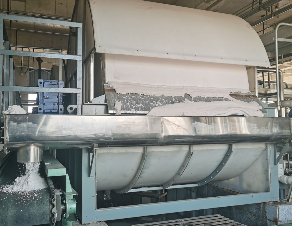
Laboratory models typically use a fixed scraper. Once the filter cake rotates out of the slurry liquid level, the scraper peels it off the drum surface.
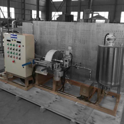
Frame and Control Panel
A support structure that integrates all components, along with switches and speed control devices for regulating drum rotation speed and starting/stopping the agitator.
Working Principle
Filtration Zone
The section of the drum that is submerged in the slurry tank. In this zone, the compartments inside the drum are connected to the vacuum system via the distributor valve. Under vacuum suction, the liquid (filtrate) passes through the filter cloth and enters the pipes inside the drum, while solid particles are trapped on the surface of the filter cloth, forming a gradually thickening filter cake.
Drying Zone
The drum exits the slurry liquid level, but the compartments remain connected to the vacuum. The vacuum continues to suction, further drawing out the residual mother liquor from the filter cake to reduce the cake’s moisture content.
Washing Zone (Optional)
If required by the process, a wash liquid spray system can be installed in this zone. The wash liquid is sprayed onto the filter cake, and the vacuum suctions it away together with the residual mother liquor, enabling displacement washing or reslurrying washing to remove impurities.
Secondary Drying Zone
The washed filter cake is again suctioned by the vacuum to remove excess wash liquid.
Discharge Zone
As the drum rotates to the scraper position, the distributor valve disconnects that compartment from the vacuum. In some designs, a brief burst of low-pressure compressed air (“blowback”; this feature is omitted if not specifically required) is introduced to help separate the filter cake from the filter cloth. The fixed scraper then removes the dried filter cake, completing the discharge process.
Filter Cloth Regeneration Zone (Optional)
After discharge, a water or air jet system may be used to clean the surface of the filter cloth. This prevents pore blockage and prepares the cloth for the next filtration cycle.
The drum rotates slowly and continuously, with the above process repeating in a cycle, enabling semi-continuous solid-liquid separation.
Floor Space
Laboratory-scale vacuum rotary drum filters are highly space-efficient equipment.
Typical Dimensions
Total System Footprint
Equipment List
Main Unit | Vacuum System |
|---|---|
Spare Parts and Tools | Agitation Tank |
|---|---|
Optional Accessories |
|---|
Applications
Laboratory-scale vacuum rotary drum filters are primarily used in the following scenarios:
Process R&D and Optimization
- Testing whether a specific material is suitable for vacuum drum filtration.
- Determining optimal filtration process parameters, such as drum speed, vacuum level, filter cake thickness, and wash liquid dosage.
- Providing key data for industrial scale-up design (e.g., filtration rate, filter cake moisture content, washing efficiency).
Small-Batch Production
Education and Training
Material Property Evaluation
Suitable Material Properties
- Solids with moderate or slow settling rates.
- Materials that form porous filter cakes with good air and water permeability.
- Solid concentrations typically ranging from 5% to 30%.
- Not suitable for handling highly viscous materials, materials that form impermeable filter cakes, or extremely fine particles (e.g., colloids)—unless filter aids are used.
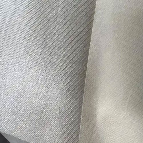
Filter Media
Filter media is the critical material covering the drum surface, and its selection directly impacts filtration performance and efficiency.Common types are as follows:
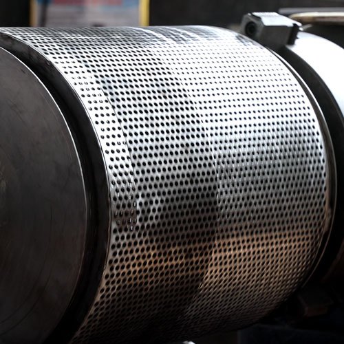
Metal Screens
Made of stainless steel or other alloys, they offer high strength, wear resistance, and easy cleaning and regeneration. Suitable for filtering coarser particles.
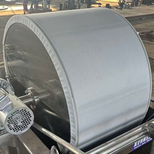
Filter Cloths
The most commonly used filter media.
- Materials: Polyester (PET), polypropylene (PP), nylon (PA), cotton, wool, etc.
- Forms: Monofilament, multifilament, or staple fiber woven cloths. Monofilament cloths have a smooth surface for easy cake discharge; staple fiber cloths have strong retention capacity but may be prone to clogging.
Composite Filter Cloths
A non-woven fabric or microporous membrane is laminated on the base cloth to achieve higher filtration precision.
Filter Papers
Disposable, used in applications requiring high cleanliness or filtration of extremely fine particles.
Selection Criteria
| Filtration Precision (Retention Capacity) | Select an appropriate pore size based on the solid particle size to ensure a clear filtrate. |
| Air/Water Permeability | Influences the filtration rate. |
| Chemical Resistance | Must withstand the chemical properties of the slurry and wash liquid. |
| Mechanical Strength | Capable of withstanding vacuum suction, scraper action, and repeated cleaning. |
| Cake Discharge Performance | Media with a smooth surface (e.g., monofilament filter cloth) allows for easier filter cake detachment. |